3 A logic system has 3 inputs and therefore 8 possible states The logic diagram representation is shown below Complete the truth table and convert the output column to hexadecimal if the state 0 is the least significant bit and the state 7 is the most significant bit 4 Give the boolean expression from the above circuit diagram 5The MSG instruction attempts to enter the queue This time the throttle position is open and the message can pass to the message queue The EW bit is set Depending on how you configure a MSG instruction, it may use a connection to send or receive data This type of message And this communication method Uses a connection CIP data table read or31 general information 32 unpacking and inspecting 33 mounting the md41( ) 34 installation limitations section 4 post installation checkout 41 preinstallation test 42 operating instructions figures list of illustrations 31 schematic pinout, 15 pin high density dsub 32 outline drawing
Icas Org
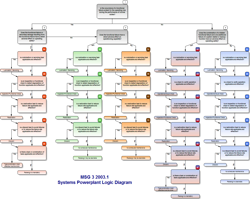
Msg-3 logic diagram
Msg-3 logic diagram-All logging messages are disabled by default To enable selected logging messages, use the ns3LogComponentEnable function or use the NS_LOG environment variable Use the environment variable NS_LOG to define a ''separated list of logging components to enable For example (using bash syntax), NS_LOG="OlsrAgent" would enable one component atReliabilitycentered maintenance (RCM) is a concept of maintenance planning to ensure that systems continue to do what their user require in their present operating context Successful implementation of RCM will lead to increase in cost effectiveness, reliability, machine uptime, and a greater understanding of the level of risk that the organization is managing


Msg90
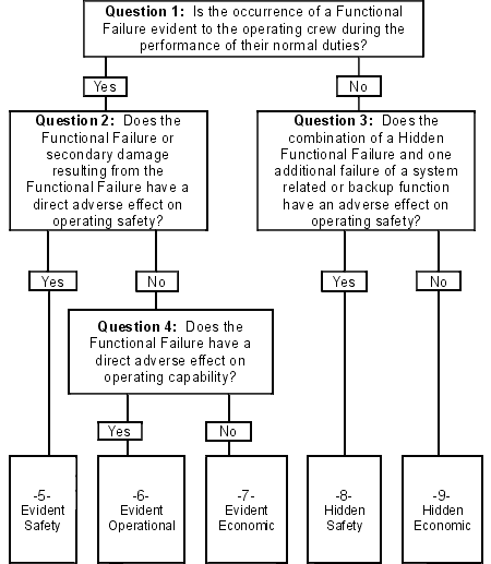
Maintenance Steering Group3 (MSG3) is a method for developing preventive maintenance programs in the aerospace industry The process is maintained by A (Airlines For America formerly known as ATA) MSG3 is a structured process for identifying Safety Significant Items (SSI), defining for each SSI the failure modes and effects (FMEA)When you print FBD logic, the editor automatically makes the logic fit the page A 21 ratio is generally readable For example, set the FBD sheet size to 11 x 17 (B Size) and print on 81/2 x 11 size paper Copy pieces of logic into other applications like Microsoft Word in aMSG3 Systems Analysis The MSG3 systems analysis is a robust procedure based on scientific logic and engineering judgment and it has evolved over the last 30 years by constantly making incremental changes based on industry experiences These changes are brought about the participation of airlines, manufacturers and regulatory agencies through
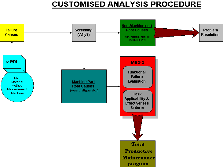
Activity Oriented FAST Diagram Facility Components Template Intstructions Versions 3/23/01 1 This is a basic Excel spreadsheet and utilizes basic Excel commands 3 The function cells are filled with sample wording for functionns The diagram needs to be edited to fit the specific study Resources Park Entrance Build Implement EstablishMSG3 is intended to facilitate the development of initial scheduled maintenance programs The remaining maintenance, that is, nonscheduled or nonroutine maintenance, consists of maintenance actions to correct discrepancies noted during scheduled maintenance tasks, other nonscheduled maintenance, normal operation, or data analysisPrior to applying the MSG3 logic diagram to an item, a preliminary work sheet will be completed that clearly defines the MSI, its function(s), functional failure(s), failure effect(s), failure cause(s) and any additional data pertinent to the item Examples include ATA chapter reference, fleet applicability, manufacturer's part number, a brief
The MSG Process introduced a decision logic into the assessment of appropriate maintenance With the introduction of MSG3 this process was refined to ensure the correct treatment of both "Safety Related" and "Economic Related" as well as including the Corrosion Protection Corrosion Prevention CPCP and Structural Integrity Program considerations includingFor all types of MSG3 analysis, MPC provides many features that help multiple users and groups to work cooperatively on their projects, while also facilitating data entry and management Userfriendly editing tools All interfaces support convenient copy/paste and a builtin spell checker that highlights spelling mistakes while you are typing Network Documentation Series Logical Diagram John W Kerns In this article, I will do a walkthrough of a logical network diagram As I also said in the Physical Diagram article I prefer to use the term "logical" instead of "L3" because it is more easily understood by somebody unfamiliar with the OSI model


Basic Steps Of Applying Reliability Centered Maintenance Rcm Part Iii


Method And User Equipment Ue For Reconnecting Rrc Connection With Radio Access Network Ran Node Ingale Mangesh Abhimanyu Et Al Samsung Electronics Co Ltd
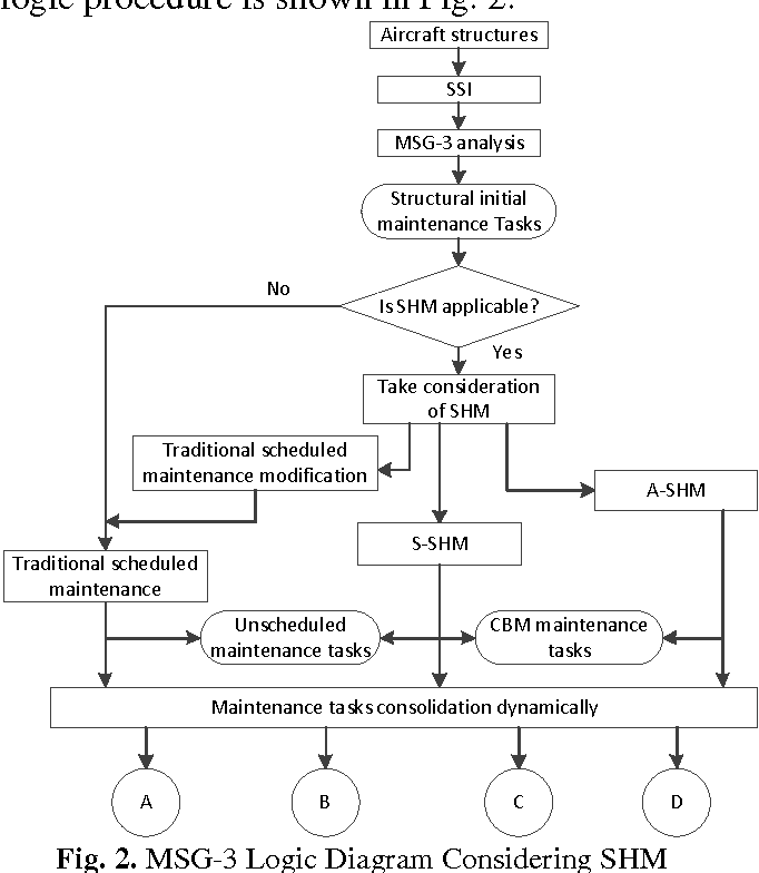
I am going to write series of tutorials on FPGA modules using spartan 3 FPGA module I will start tutorials on FPGA module soon This is a first article on series on tutorials on field programmable gate arrays FPGAs are used to design higher level of complexity circuits like customized circuits using reconfigureable gate arrays or logic cells MSG3, The Intelligent Maintenance Sign up for Aviation Pros eNewsletters SIGN UP Latest in Engines & Components Credit Lee Aerospace Windows Lee Aerospace Now Offers Learjet 55An integrated logic diagram establishes how to incorporate SHM into the current MSG3 structural analysis that is based on four maintenance scenarios with gradual increasing maturity levels of SHM The inspection intervals and the repair thresholds are adjusted according to different combinations of SHM tasks and scheduled maintenance


Easa Europa Eu
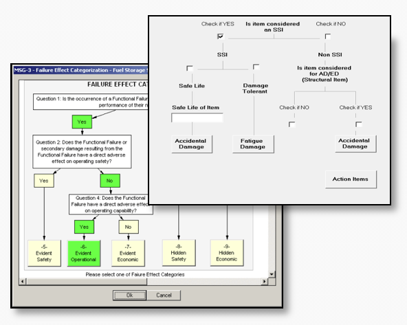


Reliability Centered Maintenance And Msg3 Dmd Solutions
CAN Introduction CAN stands for Controller Area network It is an Asynchronous serial communication protocol introduced in 1986 by Robert Bosch CAN protocol is a message based protocol not address based means transmitted data is available for all nodes and its receiver's choice to receive data or not CAN nodes are connected on two wire The arrows drawn on the schematic on the right show how to read a logframeIt does not proceed verticallyOn the contrary, it is to be read in a zigzag fashion "if we successfully deliver Outputs, then we will deliver Outcomes because we judge the change is both technically desirable and politically feasible (this is our ToC)The column on the extreme right hand of the logframeAnd FMECA (Failure Mode, Effect and Criticality Analysis)
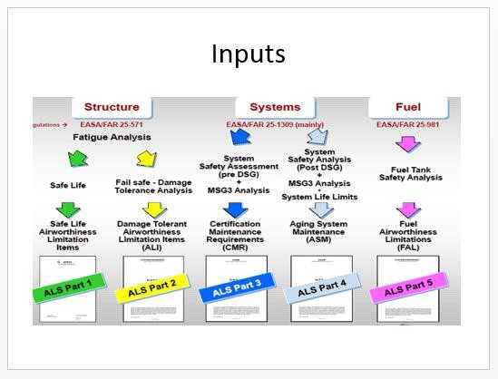


Maintenance Steering Group Fatigue Concepts
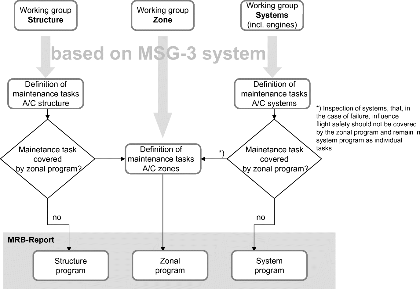


Maintenance Management Springerlink
Logic Diagrams 3 Figure 2 Example of Figure 1 Pump Start Circuit as a Logic Diagram Engineering Symbology, Prints, & Drawings Logic Diagrams 4 Symbology There are three basic types of logic gates They are AND, OR, and NOT gates Each gate is a very simple device that only has two states, on and off The states of a gate Step 3 Set up the message instruction Click the "Setup" button within the message instruction This will bring up the configuration screen Set up the MSG instruction as follows We will do a CIP data table read The source element is "Outbox" This is the tag in the target processor that we are receiving data fromMore formally, the logic diagram showing the generic communication layer in LiteOS is shown in the following figure Note that our implementation does not have a MAC layer in this example A MAC protocol could be implemented in a similar way to the routing protocol, which is also implemented as a flexible thread


Msg90
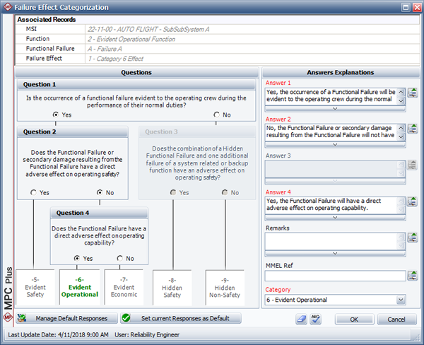


Creating Initial Scheduled Maintenance Plans For Aircraft Msg 3 Reliasoft
Others, were incorporated into the logic diagram and were routinely considered 3 MSG3 recognized the new damage tolerance rules and the supplemental inspection programs, and provided a method by which their intent could be adapted to the Maintenance Review Board (MRB) process instead of relying on type data certificate restraints This was again a logic driven process and in fact became the basis for the MSG3 process, introduced in 1980 and still in use today (with4 Pancham timing diagram The timing diagram for the input and output signals is given in Figure 1 here The number of clocks the core takes to generate msg_out_valid after msg_in_valid is asserted is unspecified and may change in future versions of


Ulrica Pen In Aviation Aircraft Maintenance What Is Msg


Msg 3 Sohar Service
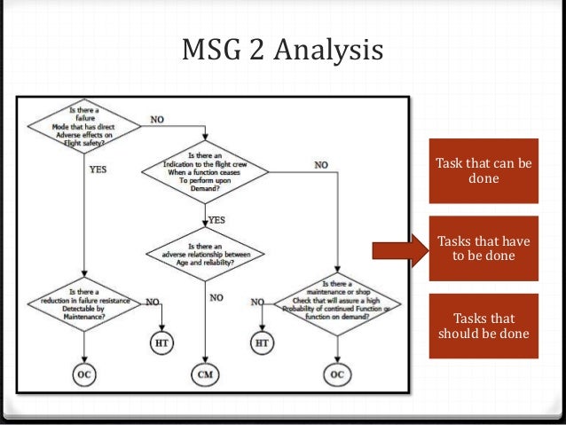
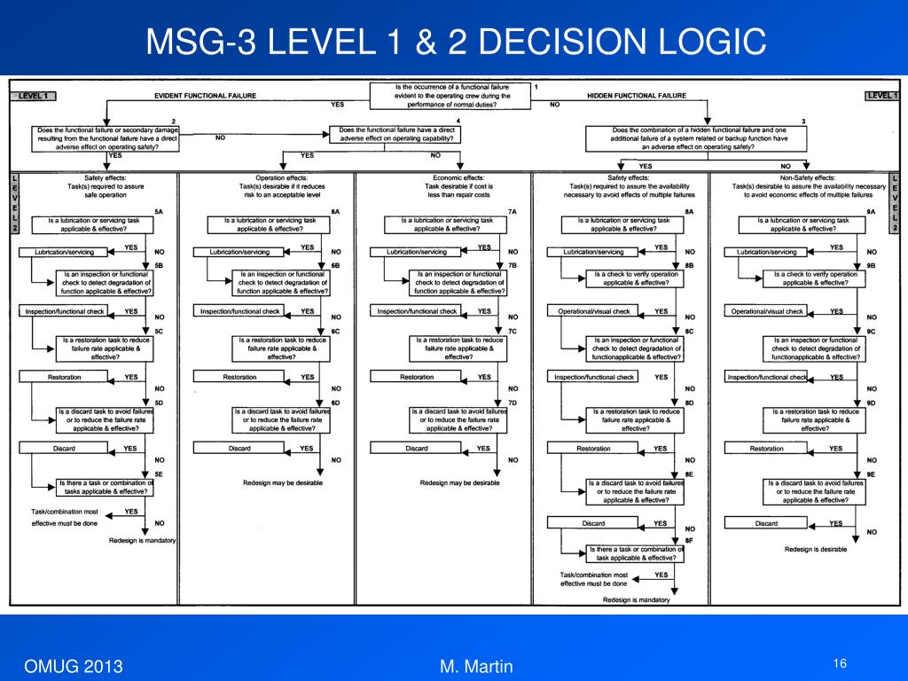
PTC Windchill MSG3 provides stepbystep guidance for identifying and scheduling maintenance tasks for aircraft in accordance with the ATA standard MSG3 (Maintenance Steering Group Version 3) Contextsensitive questions derived from the standard are structured within logicenforced diagrams to guide the analyst through MSI (MaintenanceTwo key tools are used in RCM the Decision or Logic Diagram, which is called MSG3 (Maintenance Steering Group model 3) in the aircraft industry where it evolved;According to ATA, the ATA MSG3 publication outlines a decisionlogic process for determining initial scheduled maintenance requirements for new aircraft and/or power plants This document presents a means for developing maintenance tasks and intervals acceptable to regulatory authorities, operators and manufacturers


Ata Msg 3 Maintenance Process Logic Breakdown 15 Download Scientific Diagram


Sciencedirect Com
Maintenance Steering Group 1st Task Force (MSG1) developed maintenance requirements decision and analysis logic b Role of the MSG generated new decision logic and analysis procedures contained in a new document called MSG3 8/27/12 AC C AC C 8/27/12 c BOARD Federal Aviation AdministrationProcess defined as MSG3 The process adopted a decision tree methodology with the primary purpose of a) separating safetyrelated items from economic, and b) defining adequate treatment of hidden functional failures Under MSG3 logic, activities are assessed at the system level rather than the component level – see Figure 3Windchill MSG3 provides stepbystep guidance for identi fying and scheduling maintenance tasks for aircraft in accordance with the ATA standard MSG3 (Maintenance Steering Group Version 3) Contextsensitive questions derived from the standard are structured within logicenforced diagrams to guide the analyst through MSI (Maintenance Sig
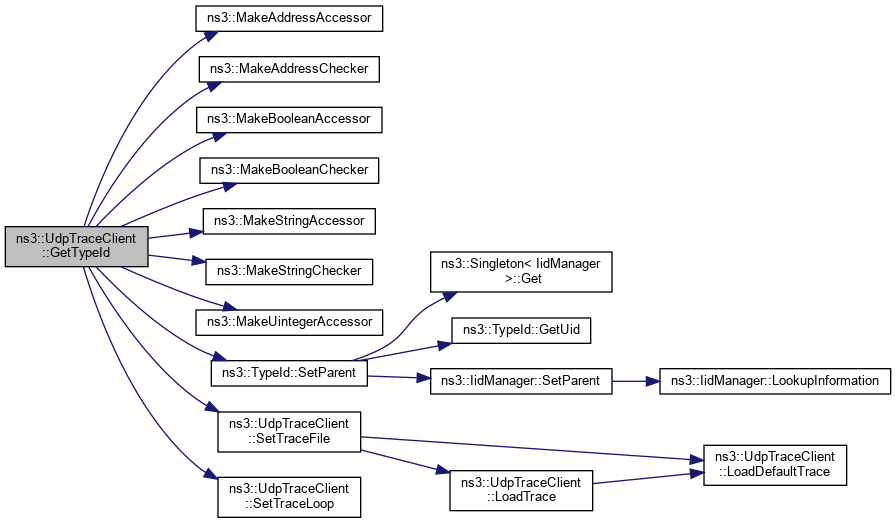


Ns 3 Ns3 Udptraceclient Class Reference


Decision Logic Diagram For System Failures Analysis Download Scientific Diagram
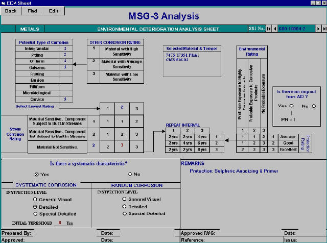


Maintenance Steering Group Environmental Deterioration Analysis Eda Flow Chart
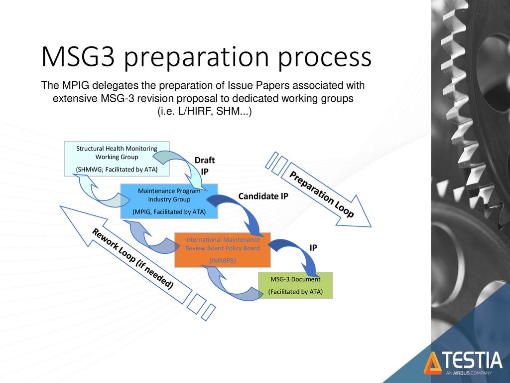


From Ndt To Shm A Practical Approach Ppt Download


Ata Msg 3 Maintenance Process Logic Breakdown 15 Download Scientific Diagram
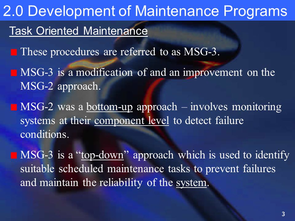


2 0 Development Of Maintenance Programs Ppt Download


Easa Europa Eu


Background Rcm


Easa Europa Eu


Decision Logic Diagram For System Failures Analysis Download Scientific Diagram


Diagram Aoa Diagramming Full Version Hd Quality Diagramming Ciruitdiagram Reverbfestival It
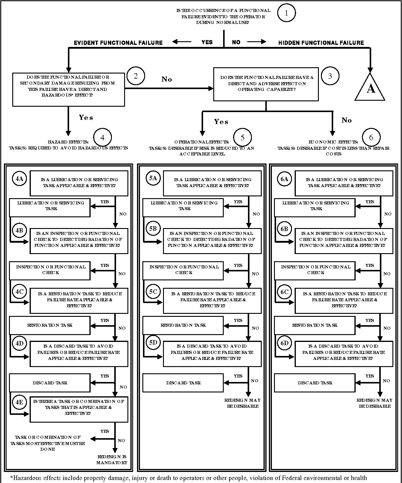


Table 3 1 From Tm 5 698 2 Reliability Centered Maintenance Rcm For Command Control Communications Computer Intelligence Surveillance And Reconnaissance C4isr Facilities Semantic Scholar


Coscap Sa Reliability Monitoring Ppt Video Online Download


Pdf4pro Com


Msg3 Revision 05 1 Pdf Reliability Engineering Data Analysis


Icao Int


Solved 1 The Billy Goat Fast Food Restaurant Sells The Chegg Com


Visor Redalyc Aircraft Preventive Maintenance Data Evaluation Applied In Integrated Product Development Process


Msg 3 Logic Diagram


Diagram Msg 3 Logic Diagram Full Version Hd Quality Logic Diagram Soadiagram Andreapendibene It


Development Of Maintenance Programs Mcgraw Hill Education Access Engineering


Applied Sciences Free Full Text An Enhanced Message Distribution Mechanism For Northbound Interfaces In The Sdn Environment Html


Icas Org


Pdf An Overview Of Trends In Aircraft Maintenance Program Development Past Present And Future Semantic Scholar


Data Transmission Method Terminal Device And Access Network Device Patent


Web Stanford Edu


Sciencedirect Com


Ppt Maintenance Steering Group 3 Msg 3 Powerpoint Presentation Free Download Id 3244


Wevj Free Full Text Battery Life Enhancement In A Hybrid Electrical Energy Storage System Using A Multi Source Inverter Html


Engmech Cz


Development Of Maintenance Programs Mcgraw Hill Education Access Engineering


Creating Initial Scheduled Maintenance Plans For Aircraft Msg 3 Reliasoft


Msg 3 Sohar Service


Msg 3 Maintenance Steering Group


Mrcet Com


Easa Europa Eu


Scielo Brasil Aircraft Preventive Maintenance Data Evaluation Applied In Integrated Product Development Process Aircraft Preventive Maintenance Data Evaluation Applied In Integrated Product Development Process


Pdf The Influence Of Shm Techniques On Scheduled Maintenance Of Aircraft Composite Structures Semantic Scholar


User Definable Rcm Decision Logic Rcm Desktop Rcm Software Written By Rcm Facilitators For Rcm Facilitators


A Smart Parking System Based On Mini Pc Platform And Mobile Application For Parking Space Detection


Aircraft Maintenance Engineering Developing Aircraft Maintenance Programme Using Reliability Centred Maintenance Msg3 Analysis And Taking Into Consideration Etops And Low Utilisation


Ns 3 Ns3 Ipv4staticrouting Class Reference


Windchill Msg 3 Relex Italia S R L


Msg 3 Maintenance Steering Group


Faa Gov


Intelligent Maintenance Program Ppt Video Online Download


Icas Org


Hangars An Overview Sciencedirect Topics


Aircraft Maintenance Program


On Aircraft Scheduled Maintenance Program Development Emerald Insight


393 Sys Airport Engineering Practice Lecture 3 Development


Ppt Reliability Centred Maintenance Rcm Powerpoint Presentation Free Download Id


Coscap Sa Legal Requirement Icao Annex 6 Para


Appendix A Enhanced Zonal Analysis Procedure Diagram


Uptime At Minimum Cost In The Process Industries


Easa Europa Eu
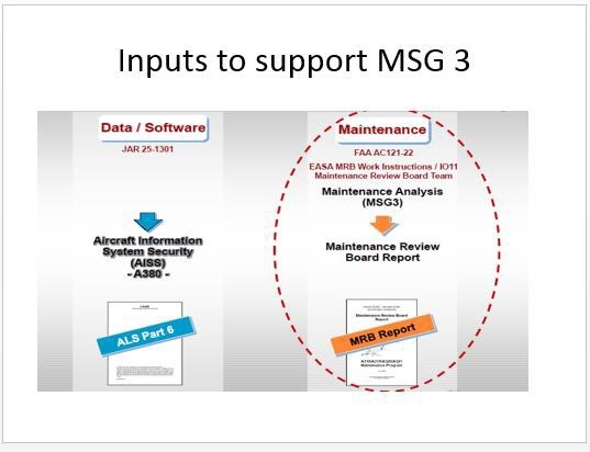


Maintenance Steering Group Fatigue Concepts


Migrating From Rabbitmq To Amazon Mq Aws Compute Blog
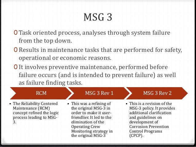


Aircraft Maintenance Program


Emerald Com


Easa Europa Eu


International Standard
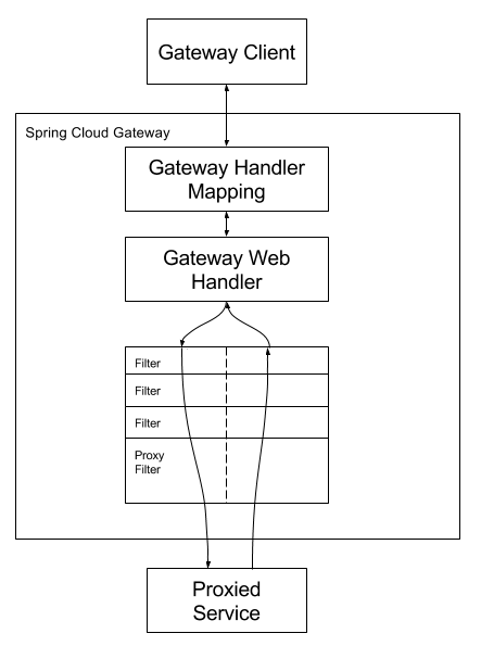


Spring Cloud Gateway


Etsi Org
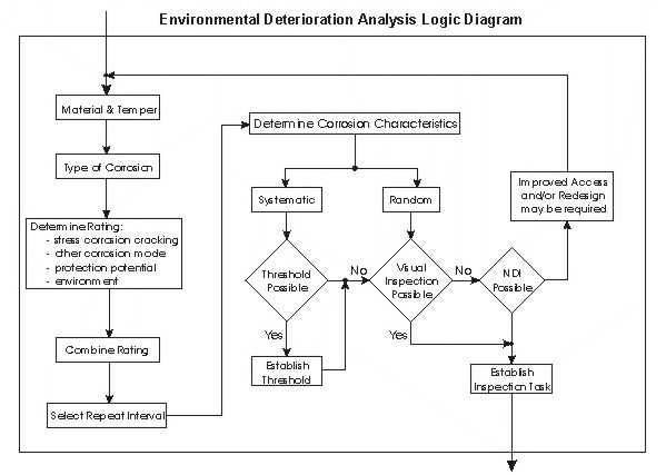


Maintenance Steering Group Environmental Deterioration Analysis Eda Flow Chart


On Aircraft Scheduled Maintenance Program Development Emerald Insight


Secure And Efficient Scheme For Fast Initial Link Setup Against Key Reinstallation Attacks In Ieee 802 11ah Networks Zhang International Journal Of Communication Systems Wiley Online Library


5 Biztalk Server Monitoring Management Solution Biztalk360
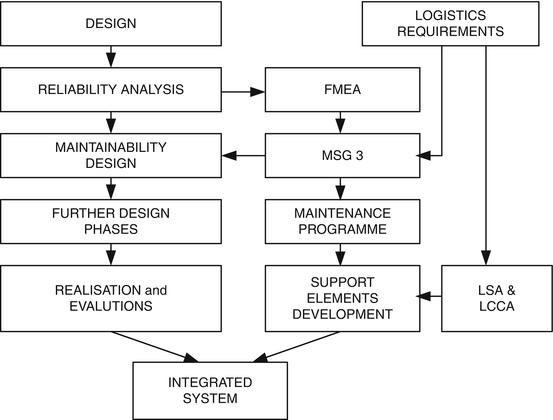


Uav Logistic Support Definition Springerlink


5g Waveform Candidate 5g Sharetechnote


Basic Steps Of Applying Reliability Centered Maintenance Rcm Part Iii


Appendix A Enhanced Zonal Analysis Procedure Diagram


Msg 3 Maintenance Steering Group
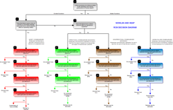


User Definable Rcm Decision Logic Rcm Desktop Rcm Software Written By Rcm Facilitators For Rcm Facilitators


Web Stanford Edu


Confluence Mobile Confluence


Msg3 Revision 05 1 Pdf Document


Icas Org


Faa Gov


Development Of Maintenance Programs Mcgraw Hill Education Access Engineering


Easa Europa Eu


Icao Int
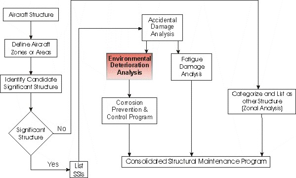


Maintenance Steering Group Structural Analysis Logic


5g Waveform Candidate 5g Sharetechnote


Ns 3 Ns3 Ipv4staticrouting Class Reference


Msg 3 Sohar Service


Msg Sports And Msg Entertainment Begin Regular Way Trading
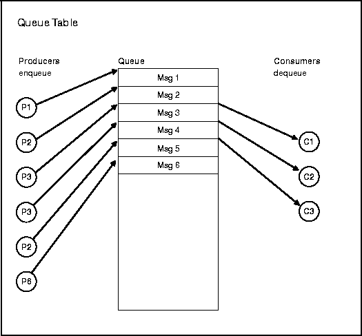


Advanced Queuing


Rcm Task Decision Tree 2 With Truncation Download Scientific Diagram


0 件のコメント:
コメントを投稿